Access
Click Features > Scheduler Builder to manage the jobs flows.
Table of Contents
Overview
The Scheduler Builder functionality allows you to create and manage the sequence of the jobs executions using a visual diagram editor. Using standardized shapes and links in the builder, you can create the job flows to show the jobs should run, one by one, from the start job to the end job.
Search
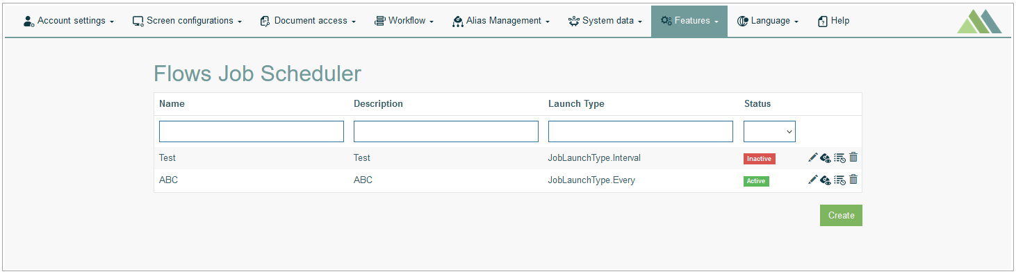
To have an overview of all flows diagrams, search for a particular job flow or filter the search results, enter Name, Description, Launch Type, Status and click the Enter key or on any screen place. The screen displays search results if found.
Navigate
Use the navigation bar at the bottom of the Overview page to navigate through the search result pages. Click the appropriate page number to open it. Use the Arrow icons to go to the next page or the previous page of the search results list accordingly.
Create Jobs Flow Diagram
Click the Create button on the Overview page to open the builder in the creation mode and create a new flow.
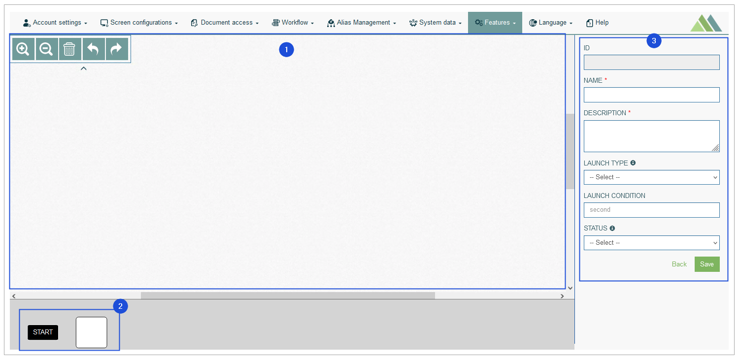
The Builder consists of 3 areas:
Drawing area
Shape library
Jobs Flow area
Let’s take a closer look at each part of the editor.
Drawing Area
In the Drawing Area, you can build the diagram using shapes, arrows and a set of the additional settings.
You can use the toolbar options by clicking the icons in the expandable/collapsible section in the top left corner of the drawing area:
Zoom In - to make the diagram picture bigger.
Zoom out - to make the diagram picture smaller.
Clear - to clear the working area and delete all diagram elements from the drawing area.
Undo - to cancel the previously done action.
Redo - to return/restore the cancelled action.
Shape Library
Shape Library contains shapes for the steps that build the Jobs flow.
A set of steps defines the sequence of jobs. Each step is connected to a particular job.
Currently, the following shapes can be used in the diagram:
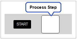
Start (Begin) step - the first step of each diagram.
Job (Process) step - a single step representing a particular job.
Note that the Start step can be used only once per flow.
Jobs Flow Area
A Jobs Flow Data section that is displayed on the right side of the drawing area shows the details and options of the flow or certain components of the diagram.
The section displays data and options depending on what element you select and highlight on the diagram.
So, this section can show the following information:
Jobs Flow Details - details about the flow.
Flow Steps Handling - the flow steps (jobs) data.
Links Handling- the parameters to set up the links between flow steps.
When creating a new flow diagram, you should first enter the data related to a diagram in the flow data section.
Jobs Flow Details
Fill in the following data:
ID - the unique identifier of the diagram. It is generated automatically.
Name - the name of the diagram that will be displayed on the Overview page and can be used for searching. This field is required.
Description - the short and clear description of the diagram.
The value will be displayed on the Overview page and can be used for searching. This field is required.Launch Type - the way of job execution:
At - the one time job execution at the particular specified date/time
Cron - this is the tool that helps you to schedule the job execution using the standard cron-expressions.
A cron expression is a string that describe individual details of the schedule:Cron Type - define the interval of the repeated job execution:
Every Day
Every Week Day
Every Weekend
Every month
Custom
Cron Settings - click the gear icon to open the Cron Settings and set up the required schedule fro the job.
Every - define the interval (in seconds) for the job execution. The job will run every period defined in seconds.
In - the job will run over the specified time period (in seconds).
Interval - the job will run with the specified interval.
Launch Condition - specify the conditions and interval in seconds that should be taken into account for the execution of the first job.
Pay attention that the Launch Condition specified here does not affect the Launch Condition defined for every single job included in the flow.
For example, the Launch Condition for job1 is 60 seconds. The job1 is included in the test1 and test2 job flows. The Launch Condition for the text1 job flow is 100 seconds. The Launch Condition for the text2 job flow is 200 seconds. In this case, the job1 will be run:
every 60 seconds, as it is defined in the job1 Launch Condition.
every 100 seconds, as the job1 is included in the text1 job flow and will have the same Launch Condition as the text1 job flow.
andevery 200 seconds, as the job1 is included in the text2 job flow and will have the same Launch Condition as the text2 job flow.
Status - the job flow status.
Note that the Status for job flow will have the higher priority than the Status defined for every single job included in the flow.
To enable/disable the job flow, select the status from the drop-down list:Active - to enable the job flow.
Inactive - to disable the work flow.
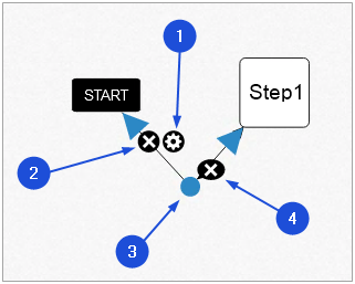
How to Build Jobs Flow
To build a new flow, perform the following actions in the Diagram editor:
Define the sequence of jobs executions that should be represented in the diagram.
Start with the Start step (BeginStep) and add it to the drawing area.
For that, drag and drop a Start shape from the shape library onto the drawing area.
This first step should be a starting point of any diagram.Drag and drop other flow steps from the shape library onto the drawing area that will represent the selected jobs.
Associate each flow step with the particular job by filling in the required data in the process step data section on the right side of the drawing area.
Link the steps to each other following the established sequence of jobs.
For this, drag connectors (arrows) from one shape and drop them on another shape to connect each step (job) in the diagram.
Pay attention that the jobs can run only in succession, one by one.
For example, the jobs flow contains 3 jobs: job1, job2, and job3.
All jobs are connected in the following way in the job flow diagram:
Start step > job1
Start step > job2 > job3
I.e., after the Start step is run, the job1 and job2 steps will be run simultaneously. The job3 step can be run only if the job2 step is finished successfully.
Edit steps using available settings and tools if needed.
Flow Steps Handling
This section contains information about flow steps (jobs) general data and tools.
Flow Step General Data
The start and every process step used in the diagram should be associated with the definite job.
The corresponding job will run according to the flow step configured.
To assign the job as well as to specify other step details, fill in the data form on the right side of the drawing area.
This form is displayed when the flow step is selected.
For the Start (BeginStep) step, the following parameters should be filled in:
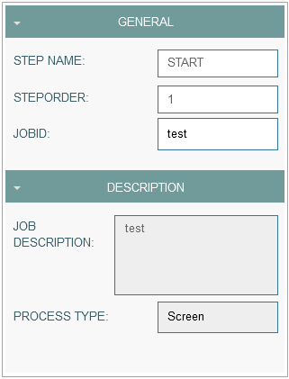
General
Step Name - the start step name. This field is predefined.
Step Order - the start step name. This field is predefined.
Job ID - select the required job ID from the list of existing jobs. The job list contains all jobs from the Job Scheduler. Regardless of the job status, whether it is active or inactive, users can select any job from the job list.
Description
Job Description - a short and informative description of the job. This field will be automatically filled in with the description according to the selected Job ID.
Process Type - the Process Type of the job. This field will be automatically filled in with the process type according to the selected Job ID.
For the Job (ProcessStep) step, the following parameters should be filled in:
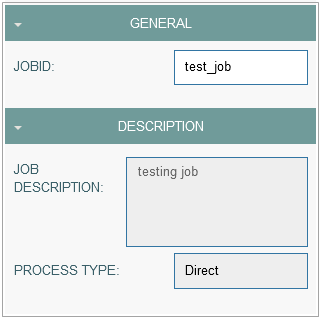
General
Job ID - select the required job ID from the list of existing jobs. The job list contains all jobs from the Job Scheduler. Regardless of the job status, whether it is active or inactive, users can select any job from the job list.
Description
Job Description - a short and informative description of the job. This field will be automatically filled in with the description according to the selected Job ID.
Process Type - the Process Type of the job. This field will be automatically filled in with the process type according to the selected Job ID.
You can find more information about the Job parameters in the Create Job section on the Job Scheduler page (Features > Job Scheduler) of the User Manual.
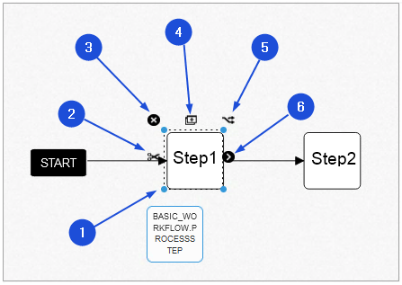
Flow Step Tools
The following operations can be performed on the process step shapes. Please use the corresponding tools to:
Resize a shape.
Delete all links (arrows) that are connected to the current shape.
Delete a shape.
Duplicate a shape.
Connect and copy a shape. Pay attention that the step name is also copied.
Link to another process step using an arrow.
Links Handling
The steps (jobs) are connected to each other via arrows. Each link (arrow) can be additionally set up:
Link Basic Data
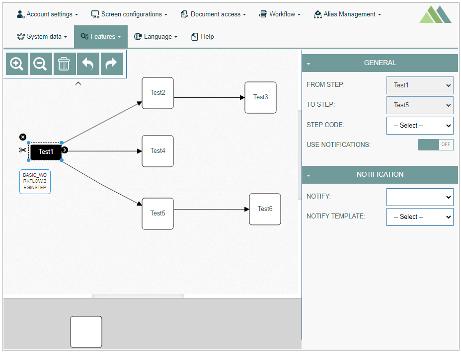
To open the Link Options section, click on the link between two shapes and then click the Settings (wheel gear) icon. The Link Options section opens in the Job Flows area.
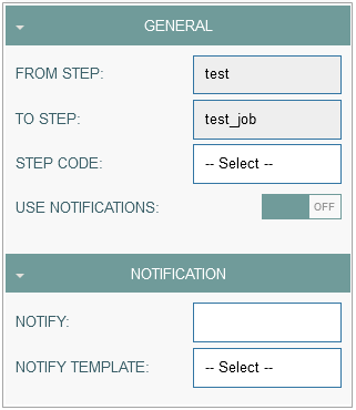
Set up the link filling in the following fields:
General
From Step - automatically filled in with the name of the step from which the link is connected.
To Step - automatically filled in with the name of the step to which the link is connected.
Step Code - select a step code from the drop-down list. The Step Code is used as an extension function that will be executed during the transition between steps.
Use Notifications - enable/disable a notification by switching on/off.
Notification
Notify - select the type of notification: SMS or email.
Notify Template - select a template for the notifications.
Link Tools
The link tools are used to set the link connecting two shapes.
The following operations can be performed on the link connecting two shapes. Please use the corresponding tools to:
Open the Link Options section.
To delete a link.
Click on any place of the link, drag the way-point appeared on the link to make a broken line.
Click the cross icon to remove the break.
Update Jobs Flow
To edit a flow diagram, click the Edit (pencil) icon for the selected entry on the Overview page. The Scheduler Builder page opens for editing.
After making the necessary changes, click the Submit button. To return to the Overview page, click the Back link.
Delete Jobs Flow
To delete a flow diagram, click the Delete icon on the Overview page for the selected entry. The confirmation pop-up will appear where you can confirm or cancel the action.