Access
Click Workflow > Workflow Builder to manage workflow diagrams for the processes and tasks.
Table of Contents
Overview
The Workflow Builder functionality allows you to create and manage the process workflow diagrams using a visual editor. A workflow diagram provides a graphic overview of the business process. Using standardized shapes and links in the workflow builder, you can create the workflows to show step by step how the process is completed from the start point to end point.
Search
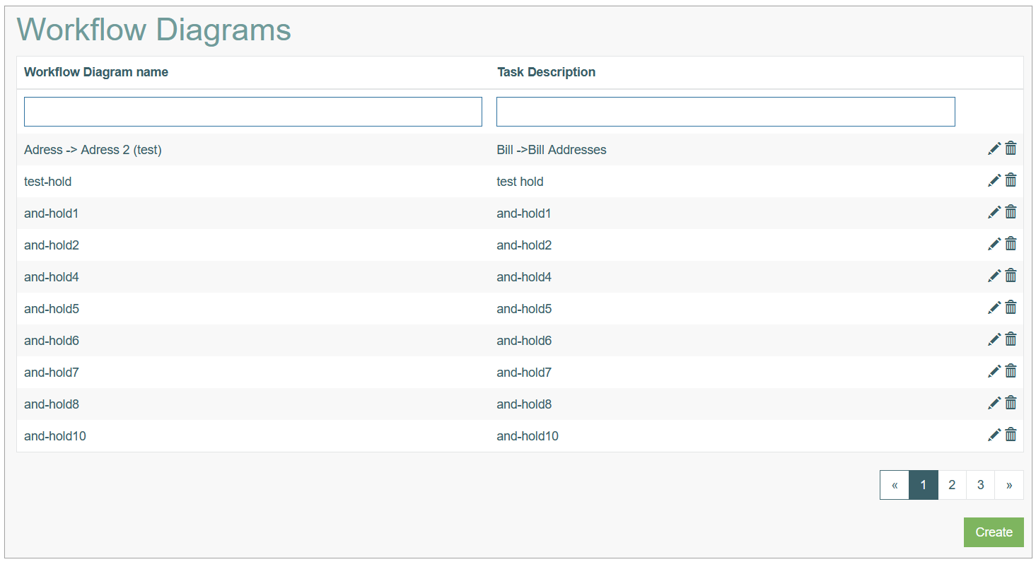
To have an overview of all workflow diagrams, search for a particular workflow or filter the search results, enter Workflow Diagram name, Task Description and click the Enter key or on any screen place. The screen displays search results if found.
Navigate
Use the navigation bar at the bottom of the Workflow Diagrams Overview page to navigate through the search result pages. Click the appropriate page number to open it. Use the Arrow icons to go to the next page or the previous page of the search results list accordingly.
Create Workflow Diagram
Click the Create button on the Workflow Diagrams Overview page to open the Workflow builder in the creation mode and create a new Workflow process.
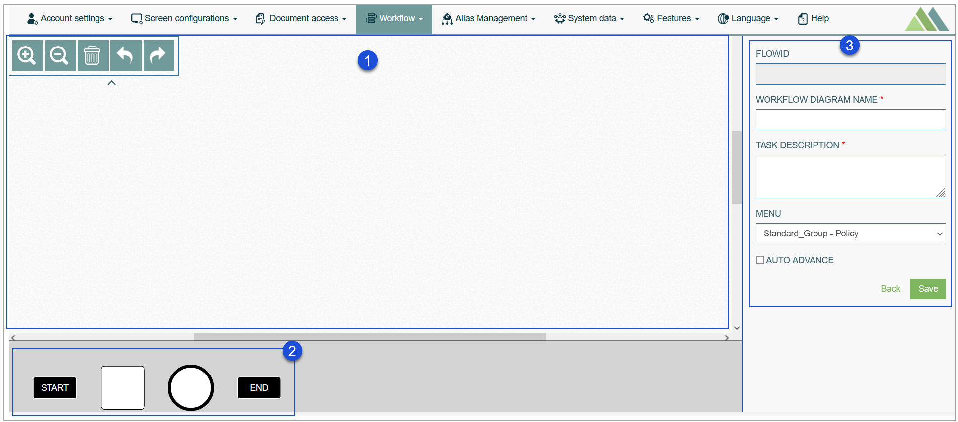
The Workflow Editor consists of 3 areas:
Drawing area
Shape library
Workflow diagram data
Let’s take a closer look at each part of the editor.
Drawing Area
In the Drawing Area, you can build the diagram using shapes, arrows and a set of the additional settings.
You can use the toolbar options by clicking the icons in the expandable/collapsible section in the top left corner of the drawing area:
Zoom In - to make the diagram picture bigger.
Zoom out - to make the diagram picture smaller.
Clear - to clear the working area and delete all diagram elements from the drawing area.
Undo - to cancel the previously done action.
Redo - to return/restore the cancelled action.
Shape Library
Shape Library contains shapes for the steps that build the process workflow.
A set of steps defines the sequence of activities required to complete a specific process or task. Each step is connected to a particular screen that configured for a specific task. Going through the workflow, the user will be redirected from screen to screen according to the sequence of steps defined in the workflow diagram.
Currently, the following shapes can be used in a workflow diagram:
Start (Begin) step - the first step of each diagram. This step is activated by the Insert action on the selected screen.
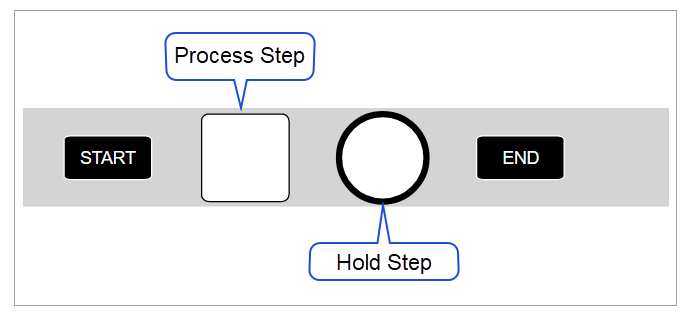
Process step - a single activity step representing a part of the process. This step is activated by the Edit action on the selected screen.
Hold step - a conditional step of the diagram. This step contains a certain hold condition that prevents the transition to the next step until the required actions are done. E.g. notifications to SMS, Chat, Email, etc. The transition from this step to the next step can only be initiated from a custom plugin or by manually editing the task on the Tasks page (Workflow > Tasks) in the Architect application. For more details about the task editing, refer to the Update Task section on the
Tasks page of the User Manual.End step - the last step of a diagram that closes the process.
Note that the Start and End steps can be used only once per workflow.
Workflow Data
A workflow diagram data section that is displayed on the right side of the drawing area shows the details and options of the workflow diagram or certain components of a diagram. The section displays data and options depending on what element you select and highlight on the diagram.
So, this section can show the details for:
Workflow diagram
Workflow diagram steps (Start, Process, Hold, End)
Links between the diagram steps
When creating a new workflow diagram, you should first enter the data related to a diagram in the workflow data section. Fill in the following data:
Flow ID - the unique identifier of the diagram generated automatically.
Workflow Diagram Name - the name of the diagram that will be displayed on the Overview page and can be used for searching.
Task Description - the short and clear description of the diagram. The value will be displayed on the Overview page and can be used for searching.
Menu - select the menu from the drop-down list of available menu items. The created workflow steps will be assigned to the selected menu and will be displayed at the top of the page in the Render application.
Auto Advance - select the check box to activate the Auto Advanced mode. The Auto Advance mode allows users to create a simple one-way process without conditional steps. In this mode, you cannot assign an executor to a process and specify the next step, and switching between steps and screens occurs automatically after completing the action on the screen. Select the check box to activate the Auto Advance mode.
How to build a workflow diagram
To build a new process diagram, perform the following actions in the Workflow Diagram editor:
Define the workflow stages and sequence of steps that should be represented in the diagram.
Start with the Start step (BeginStep) and add it to the drawing area.
For that, drag and drop a Start shape from the shape library onto the drawing area. This first step should be a starting point of any diagram.Drag and drop other process steps from the shape library onto the drawing area.
Associate each process step with the definite screen by filling in the required data in the process step data section on the right side of the drawing area.
Drag connectors (arrows) from one shape and drop them on another shape to connect each step in the diagram.
Link the steps to each other carefully following the established sequence of steps.Edit steps using available settings and tools if needed.
Process Steps Handling
This section contains information about process steps' general data and tools.
Process Step Basic Data
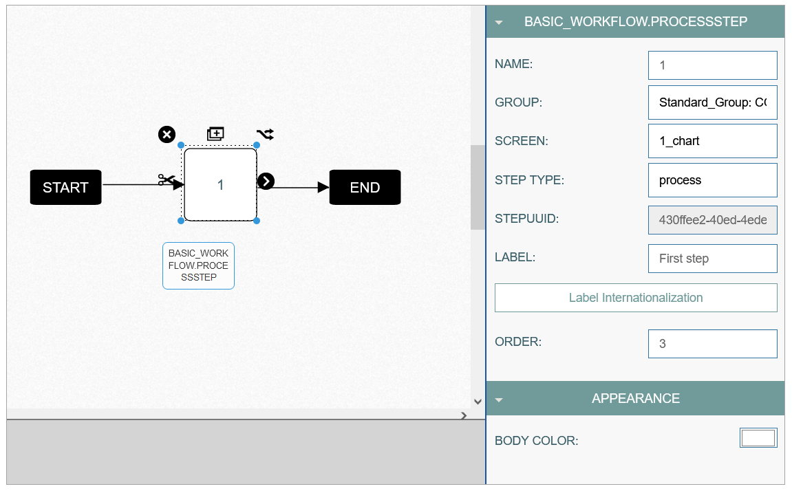
Every process step used in the diagram (except for the End step) should be associated with the definite screen. The corresponding screen will appear in the Render application according to the workflow step configured. To assign the screen as well as to define the process step details, fill in the data form on the right side of the drawing area. This form is displayed when the process step is selected.
Fill in the following parameters:
Basic data
Name - enter step name displayed on the shape in the diagram.
Group - select the user group from the drop-down list, for which the step will be available.
Screen - select the screen that will be associated with the process step.
Step Type - the type of step is pre-defined and corresponds to the selected shape.
The supported types are:Start step
Process step
Hold step
End step
Step ID - the unique identifier of the step generated automatically.
Label - the title displayed in the sequence of steps in the Render application.
Label Internationalization - the translations of the label done into other languages. Click the button to add a new translation.
Order - enter a number that will define the step order number in the whole chain of the steps.
Appearance
Body Color - select the fill color of the shape.
See the screenshot below:
If the workflow tracker viewable checkbox is enabled in the selected screen’s settings, the workflow tracker will be displayed on that screen, allowing users to monitor progress and status updates. If this option is not checked, the workflow tracker will be hidden for that screen.
Process Step Tools
The following operations can be performed on the process step shapes. Please use the corresponding tools to:
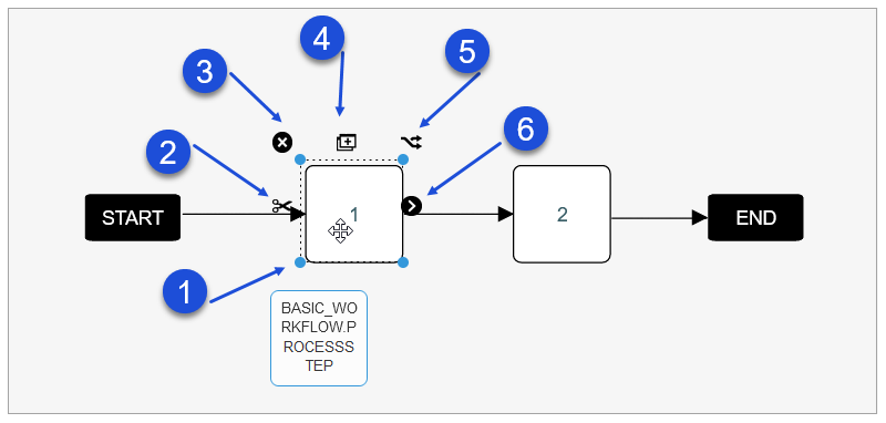
Resize a shape.
Delete all links (arrows) that are connected to the current shape.
Delete a shape.
Duplicate a shape.
Connect and copy a shape. Pay attention that the step name is copied, too.
Link to another process step using an arrow.
Links Handling
The process steps are connected to each other via arrows. Each link (arrow) can be additionally set up:
Link Basic Data
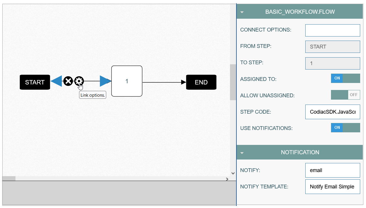
To open the Link Options section, click on the link between two steps and then click the Settings (wheel gear) icon. Set up the link filling in the following fields in the section opened on the right side of the drawing area:
Basic data
Connect Options - this is a label for link. It is not used in the Render.
From Step - automatically filled in with the name of the step from which the link is connected.
To Step - automatically filled in with the name of the step to which the link is connected.
Assigned To - is used to specify that the target step has a specific assigned user. This means that in the Render, the system will look at the group on the target step to generate the list of users for assignment.
Allow Unassigned - is used to specify whether the task can be moved to the next step if no assignee has been selected. In case the check box is activated, that means that the target step can have unassigned tasks.
Step Code - is used as an extension function that will be executed during the transition between steps.
Use Notifications - enable/disable a notification by switching on/off.
Notification
Notify - select the type of notification: SMS or email.
Notify Template - select a template for the notifications.
Link Tools
The following operations can be performed on the link connecting two shapes. Please use the corresponding tools to:
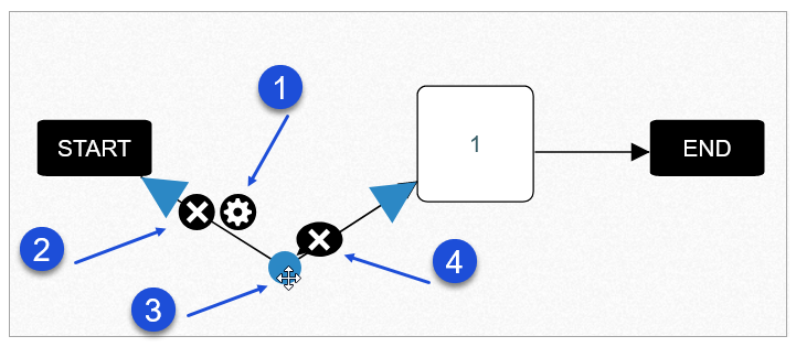
Open the Link Options section.
To delete a link.
Click on any place of the link, drag the way-point appeared on the link to make a broken line.
Click the cross icon to remove the break.
Update Workflow Diagram
To edit a workflow diagram, click the Edit (pencil) icon for the selected entry on the Overview page. The Workflow Builder page opens for editing.
After making the necessary changes, click the Save button. To return to the Overview page, click the Back link. Note that these buttons are available by clicking on an empty space on the diagram.
Delete Workflow Diagram
To delete a workflow diagram, click the Delete icon on the Overview page for the selected entry. The confirmation pop-up will appear where you can confirm or cancel the action.